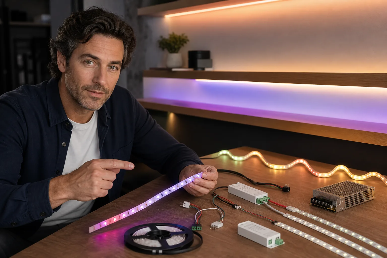
An LED strip showing wrong colors usually has one of four problems: the controller is assigning commands to the wrong color channels, a connector is reversed or offset, the strip and controller are incompatible, or one color channel has a poor connection or has failed. Start by selecting pure red, green and blue one at a time in the app or remote. Record what the strip actually displays, then use the checks below to separate a settings problem from a wiring or hardware fault. Disconnect power before touching connectors, copper pads or wiring.
Start with a three-color channel test
Full-color strips create colors by varying separate red, green and blue outputs. The U.S. Department of Energy explains that RGB and related color-tunable products use three or more LED primaries that can be controlled individually to produce saturated colors, tints and mixed white light. That separate-channel design is why one crossed or missing connection can change every mixed color. DOE guidance on color-tunable LED products provides additional background.
Run the test without scenes or effects
- Cancel music modes, gradients, animated scenes and schedules.
- Set brightness to a moderate level rather than the minimum or maximum.
- Select pure red and note the displayed color.
- Repeat with pure green and pure blue.
- If the product has a separate white channel, test that channel independently.
Test the entire strip rather than looking only at the first LED. A uniform error along the full run points toward mapping, settings or controller compatibility. A fault that begins after a connector, cut or corner is more likely to be a physical connection problem.
| Command | What appears | Likely meaning | First check |
|---|---|---|---|
| Red | Green or blue | Channels are mapped in the wrong order | App channel-order setting and R/G/B terminal labels |
| Green | Red or blue | Channels are mapped in the wrong order | Connector orientation and controller configuration |
| Any single color | No light | That channel is open, disconnected or damaged | Pin contact, copper pad, cable and controller output |
| White | Cyan | Red is missing or very weak | Red-channel connection |
| White | Magenta | Green is missing or very weak | Green-channel connection |
| White | Yellow | Blue is missing or very weak | Blue-channel connection |
| Any color | Correct near the controller, wrong farther away | Connection damage or inadequate power distribution | Joints, run length, cable size and power plan |
The white-color clues in the table apply to RGB mixing, where all three channels contribute to white. An RGBW strip has a separate white channel, so its behavior can differ depending on how the controller generates white.
Correct software mapping and smart-light settings
If every section of the strip consistently swaps two colors, inspect the controller settings before changing any wiring. Controllers may offer channel orders such as RGB, RBG, GRB, GBR, BRG or BGR. Addressable strips may also have a device-specific color order selected during setup.
Look for these settings
- Color order or channel sequence: Change this only if the controller provides an explicit option.
- Strip type: Confirm that RGB, RGBW, RGB+CCT or the appropriate addressable chipset is selected.
- Segment or pixel count: An incorrect count usually affects effects and zones, but it can also make addressable-strip behavior appear erratic.
- Calibration or white balance: Return custom calibration values to their defaults if colors became wrong after adjustment.
- Scenes and automations: Disable schedules, music synchronization, adaptive modes and third-party routines during diagnosis.
- Grouped devices: Confirm that the app is controlling the intended strip and not applying a scene designed for another product.
Smart-lighting features vary substantially among products. ENERGY STAR notes that app-controlled lighting may include dimming, tunable white, full-color selection, scenes and schedules, so an unexpected automation or mode can imitate a hardware problem. ENERGY STAR's smart-lighting overview describes these common control features.
If the strip previously worked, restart the controller and reopen the app. Use a factory reset only after recording network details, scenes and automations, because reset procedures differ by manufacturer. Install firmware updates only through the product's official app or documented process.
Check connector direction and channel order
Disconnect the power supply from the receptacle before opening a clip connector or moving conductors. Do not rely only on the insulation colors of an extension cable. Read the printed labels on the strip and controller: these may include a positive-voltage mark such as 12V or 24V, plus R, G, B and sometimes W, CW or WW.
Inspect plug-in and clip connectors
- Make sure the connector is not shifted sideways by one copper pad.
- Match each labeled strip pad to the corresponding controller or extension conductor.
- Check that the strip is inserted fully and squarely under the contacts.
- Look for folded contacts, lifted copper pads, corrosion, scorching or adhesive trapped between contact surfaces.
- Verify that corner connectors and extension leads preserve the same channel order from end to end.
- Do not assume that arrows have the same meaning on every product. On addressable strips, an arrow commonly indicates data direction; on other assemblies, markings may identify alignment or polarity.
Many analog RGB strips use four conductors: a common supply connection and separate red, green and blue channels. RGBW commonly adds another conductor, while tunable-white and addressable products use different arrangements. A connector with the correct number of pins can still be electrically incompatible.
Replace a loose, overheated or damaged connector with a component specified for that strip width, conductor count, current and environment. Avoid improvised mains-side repairs. UL emphasizes that connectors are evaluated for particular power, control and signal applications; suitability depends on the actual component and installation. UL connector certification information explains this application-specific approach.
Confirm the controller and strip are compatible
A controller cannot be chosen by connector shape alone. Before reconnecting the system, compare the labels or manuals for the strip, controller and power supply.
Match all four characteristics
- Voltage: The controller and power supply must support the strip's marked input voltage. Do not connect a 5-volt strip to a 12- or 24-volt supply.
- Control method: An analog constant-voltage RGB strip requires a different controller from a digitally addressable strip.
- Channel type: RGB, RGBW, RGB+CCT and single-color systems require the appropriate outputs and software configuration.
- Addressable protocol and direction: Digital strips require a controller that supports their chipset or protocol, with data entering at the designated input end.
Incompatible digital protocols may produce random colors, flickering, frozen pixels or no response. Stop testing if a strip or controller becomes unusually hot, smells burnt or shows visible discoloration. Disconnect it and replace the damaged component according to the manufacturer's instructions.
Trace a missing or weak color channel
If red, green or blue is absent, find where the failure begins. A missing channel across the entire strip can indicate a controller output, first connector or main lead problem. If the first section is correct but everything after a join is wrong, inspect that join. One isolated group of LEDs displaying the wrong color generally points to local strip damage rather than app mapping.
Use location to narrow the fault
- Wrong from the first LED onward: Check settings, controller type and the first connection.
- Wrong after a clip or soldered joint: Check alignment and continuity at that joint.
- One short section is wrong: A copper trace, component or LED package may be damaged.
- The error changes when the strip moves: Stop flexing it; an intermittent conductor or connector is likely.
- The end becomes dim or changes hue at high brightness: Review the power supply, cable length and injection plan.
Do not press, bend or reconnect an energized strip to make the color return. Intermittent contact can create heat, and repeated flexing near cut points may worsen damaged copper traces. A replaceable section may be removed only at a manufacturer-marked cut line and only if the product instructions permit field cutting and reconnection.
Rule out an undersized power supply or long run
Power problems more often cause dimming, instability or color changes near the far end than a clean red-to-green swap along the entire strip. Still, a long run can look like a color-channel fault when one channel becomes noticeably weaker at high output.
Estimate the required capacity
For a constant-voltage strip, a useful planning estimate is:
Required supply watts = strip length × rated watts per unit length × headroom factor
For example, assume a 5-meter strip rated at 14.4 watts per meter and a 20% planning margin:
5 m × 14.4 W/m × 1.20 = 86.4 W
That estimate suggests a supply rated for at least 86.4 watts at the strip's exact voltage; the next suitable standard size might be 90 or 100 watts. The 20% margin is a planning assumption, not a universal requirement. Follow the strip and power-supply manufacturers' loading, ventilation and derating instructions. Ross Lighting's LED strip power calculator can help with the arithmetic.
If only the distant end changes color, reducing brightness temporarily can help distinguish a distribution problem from fixed channel damage: improvement at lower output supports, but does not prove, a power-delivery issue. Permanent corrections may require shorter runs, manufacturer-approved power injection or larger conductors. Because incorrect power injection can cause excessive current or short circuits, use an electrician or qualified low-voltage lighting installer when the design is not explicitly covered by the product documentation.
Know when to repair, replace or call an electrician
Replace a removable connector when its contacts are visibly damaged and an exact, manufacturer-compatible replacement is available. Replace a strip section when one local segment has a permanent missing channel and the strip is designed to be cut and rejoined. Replace the controller when its settings are correct but one output remains dead across a known-compatible strip, subject to the manufacturer's diagnostic procedure and warranty terms.
Stop and consult a licensed electrician if troubleshooting involves fixed building wiring, a hardwired driver, an opened mains-voltage enclosure, damaged receptacles, exposed line-voltage conductors, repeated breaker trips or signs of overheating. Low-voltage LEDs do not make the mains input side of the power supply safe to service.
For a new layout, test the complete strip, controller and connectors before mounting them permanently. Plan strips as accent, shelf or under-cabinet lighting rather than assuming they will provide all the general and task light a room needs. See the guides to installing LED strip and layered lighting for placement and room-lighting considerations.
Frequently asked questions
Why does my LED strip show green when I select red?
The red command is probably being sent to the green channel. Check the app's RGB channel-order setting, then compare the R, G and B labels on the strip, connector and controller. Disconnect power before changing a physical connection.
Why is my RGB strip cyan instead of white?
RGB white normally uses red, green and blue together. Cyan usually means the red channel is missing or weak. Inspect the red-channel pin, copper pad, extension wire and controller output, starting where the color first becomes incorrect.
Can low voltage make an LED strip display the wrong color?
It can contribute to dimming, instability or a color imbalance, especially near the end of a long run at high brightness. A clean color swap across the whole strip is more likely to be channel mapping or connector order.
Will any four-pin controller work with a four-pin LED strip?
No. The voltage, common connection, channel arrangement, power rating and control method must all match. Similar-looking connectors do not guarantee electrical compatibility.
Questions & discussion
Share a question or a useful experience about this guide. Comments appear immediately. Your name and comment are public. Email is optional and stays private; reply emails are not enabled yet. Comment privacy.