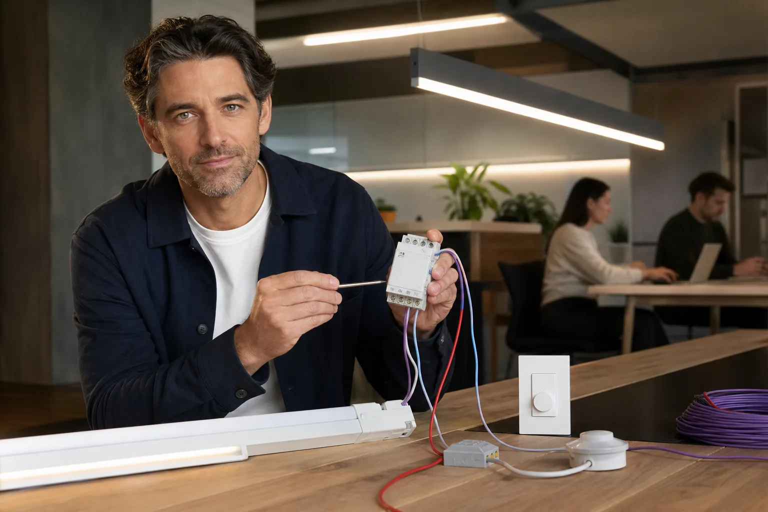
0-10V dimming explained simply: a controller sends a low-voltage direct-current signal to a compatible LED driver, and the driver adjusts the fixture's light output in response. A higher control voltage generally requests more light; a lower voltage requests less. The system normally uses two control conductors in addition to the fixture's mains power wiring. It is common in commercial luminaires, offices, workshops and larger residential projects where multiple fixtures must dim together smoothly.
The name can be misleading, however. It does not guarantee that 5 volts produces exactly 50% light, that every fixture reaches the same minimum level or that reducing the signal to zero switches the fixture off. The driver, controller and switching arrangement must be selected as a compatible system.
What does 0-10V mean?
Volts carry the instruction, not the lighting load
A volt, abbreviated V, is a unit of electrical potential. In this application, the nominal 0-to-10-volt signal communicates a requested dimming level. It is not normally the power source for the LEDs. The fixture still receives its rated line voltage, such as 120V or 277V, while its LED driver interprets the separate control signal.
The common architectural approach uses two polarized control connections, marked positive and negative. The LED driver typically supplies a small control current, and the wall control or control module regulates the resulting voltage by sinking that current. The U.S. Department of Energy notes that current-sourcing and current-sinking versions both exist, so products should not be combined merely because each carries a 0-10V label. DOE research on 0-10V control methods explains this distinction and documents variation among drivers.
Control voltage is not a direct brightness percentage
A quick conceptual estimate is:
Requested fraction = control voltage ÷ 10
Under that simplified assumption, 7V represents a 70% command. It does not prove that the fixture will emit 70% of its rated lumens. Drivers may use linear or nonlinear response curves, may reach full output before 10V and may stop reducing output at a specified minimum. Human brightness perception is also nonlinear, so a fixture at 50% measured light output may appear brighter than “half brightness.” Use the manufacturer's dimming curve when an exact result matters.
Zero volts does not always mean off
Traditional architectural current-sinking systems historically defined maximum output near 10V and a manufacturer-dependent minimum near 1V without necessarily defining an off state. A relay or mechanical switch may therefore be needed to disconnect line power. Newer drivers may support dim-to-off or standby behavior, but that feature must appear explicitly in the driver and control documentation. Do not use “0-10V,” “dims to 1%” and “dims to off” as interchangeable claims.
How a complete 0-10V system works
A basic installation contains four functional elements:
- Light source: usually an integrated LED module rather than a conventional replaceable household bulb.
- Compatible driver: converts line power to the electrical output required by the LEDs and responds to the control signal.
- 0-10V controller: a wall station, sensor, control module or building-control interface that sets the signal level.
- Switching device: a switch or relay that turns line power off when the selected driver does not provide a dependable electronic off state.
Fixtures connected to the same pair of control conductors usually form one zone and receive the same command. This is simple and useful, but it does not normally provide individual addressing. If six downlights share one control pair, they behave as a group unless the system includes additional control hardware.
The maximum number of drivers on one control output depends partly on the controller's current-sinking capacity and the control current contributed by each driver. A preliminary calculation is:
Maximum theoretical driver count = controller sink-current rating ÷ control current per driver
For example, a 50 mA control output divided by drivers rated at 0.5 mA each gives a theoretical count of 100. That is not an installation limit by itself. Apply the lower limit stated by the control manufacturer, account for conductor length and voltage drop, and confirm whether other devices share the output. A lighting-controls designer or electrician should verify large zones.
When 0-10V dimming matters
Good applications
0-10V is especially useful when a room has several compatible fixtures that should respond together. Typical examples include rows of office luminaires, recessed fixtures in an open-plan room, workshop lighting, high-bay fixtures and installations linked to occupancy or daylight sensors. It can also suit residential projects using architectural-grade integrated fixtures, provided the extra control wiring is planned before walls and ceilings are closed.
Compared with phase-cut dimming, the control instruction is carried on separate conductors instead of being encoded by modifying the AC power waveform. The Department of Energy identifies 0-10V, DALI and DMX as control options that use separate control wiring and may offer better resolution or smoothness than phase-cut control in some color-tunable systems. DOE guidance on color-tunable LED controls also emphasizes that the complete luminaire and control arrangement affects performance.
When another control method may be more practical
0-10V is not automatically the best option for a table lamp, a single replaceable A19 bulb or a retrofit where only standard line-voltage wiring reaches the wall box. A compatible phase-cut LED dimmer may be simpler in those situations. Digital systems such as DALI may be more appropriate when fixtures require individual addresses, two-way status reporting or flexible regrouping. Wireless controls can reduce new control cabling, although they introduce their own commissioning and interoperability requirements.
| Project condition | 0-10V suitability | Reason |
|---|---|---|
| Multiple integrated LED fixtures in one zone | Often suitable | One control signal can dim the group together. |
| Single household bulb on existing wiring | Usually unnecessary | A listed bulb-compatible phase-cut dimmer is generally simpler. |
| Occupancy and daylight control | Often suitable | Sensors can request intermediate output instead of only on or off. |
| Individual fixture monitoring or regrouping | Limited by itself | Basic analog control is one-way and zone-based. |
| Finished room without control conductors | Potentially disruptive | New cable routes and wall work may be required. |
Plan the room, layers and control zones together
Separate lighting by purpose
A useful layered lighting plan combines ambient, task and accent light. Those layers should not necessarily share one dimming zone. Ambient downlights might form one zone, work-surface pendants a second and wall-washing or display fixtures a third. Independent zones let people reduce general brightness without making a desk, counter or stair unsafe to use.
Group fixtures when they serve the same activity, need the same schedule and have compatible drivers and dimming curves. Avoid mixing unrelated driver models on one visible row unless their coordinated performance has been documented. DOE testing has shown that market-available drivers receiving the same signal can produce different light levels, dead zones or minimum outputs.
Estimate light levels before selecting the dimming range
Rated lumens describe light leaving a source; lux describes lumens incident on each square meter. A planning estimate for average illuminance is:
Average lux = total fixture lumens × coefficient of utilization × light-loss factor ÷ area in square meters
Assume, for example, eight fixtures rated at 1,000 lumens, a coefficient of utilization of 0.60, a light-loss factor of 0.80 and a 20 m² room:
8 × 1,000 × 0.60 × 0.80 ÷ 20 = 192 lux
If the drivers genuinely provide 10% light output at minimum, the same simplified model suggests about 19 lux before considering daylight or other layers. This is only an average estimate: ceiling height, beam angle, room reflectance, fixture spacing and surface location can create significant variation. Use the lumens calculator for early planning and a project-specific lighting calculation for critical work areas.
How to choose compatible fixtures and controls
Start with the fixture or driver data sheet, not the control's faceplate. A product described only as “dimmable” may be designed for leading-edge, trailing-edge, proprietary, wireless or another control method rather than 0-10V.
Specification checklist
- Confirm that both the driver and controller identify the same 0-10V control method.
- Check the stated minimum output, such as 10%, 1% or 0.1%, and whether that value refers to light output, driver current or power.
- Determine whether the driver dims to off or requires separate line-voltage switching.
- Compare linear versus logarithmic dimming curves when several fixture types must appear to track together.
- Verify the controller's maximum load, control-current capacity and permitted number of drivers.
- Check whether the control requires a neutral conductor, relay module or separate power pack.
- Use the documented conductor type, polarity, routing and maximum distance.
- Confirm behavior after a power interruption, including default output and sensor settings.
- Request a compatibility statement or approved equipment schedule when one is available.
Compatibility evidence matters even when products meet general performance requirements. As one relevant benchmark, ENERGY STAR requires covered dimmable downlights to disclose their dimming range and provide compatible-control information or known limitations. ENERGY STAR downlight criteria apply specifically to that product category, but the same documentation-first approach is useful for other fixtures.
Also choose light quality independently of the control protocol. Compare lumens, color temperature, color rendering, beam angle and glare control. Standard 0-10V dimming usually changes intensity without changing color temperature. A warm-dim or tunable-white fixture requires a driver and control arrangement specifically designed for that function.
Troubleshooting and electrical safety
| Symptom | Possible cause | Appropriate next step |
|---|---|---|
| Fixture stays at full output | Open control circuit, wrong control type or disconnected conductors | Have the control path and product compatibility checked. |
| Fixture remains at minimum | Shorted control pair, reversed or incorrect connections, or failed control | Switch off the circuit and have wiring tested against the manuals. |
| Lights do not turn fully off | Driver has a minimum output and no dim-to-off function | Confirm whether a listed relay or switch is required. |
| Fixtures dim unevenly | Mixed drivers, different dimming curves or excessive zone loading | Compare driver models and divide the zone if necessary. |
| Output jumps or stalls | Driver dead zone, limited control resolution or incompatible components | Review dimming curves and manufacturer compatibility data. |
| Visible flicker or buzzing | Driver, control, wiring or power-quality problem | Use the LED flickering guide or LED buzzing guide, then obtain qualified diagnosis. |
Although the control signal is low voltage, the same fixture, junction box or control enclosure may contain hazardous line voltage. Wired LED-driver controls are addressed by product safety requirements, including isolation and Class 2 considerations under UL 8750. UL's overview of wired LED control requirements shows why installers should follow the product's markings rather than assume every 0-10V circuit can be handled or routed in the same way.
Use a licensed electrician whenever work involves branch-circuit conductors, junction boxes, new control cable, relays, driver replacement or uncertainty about circuit classification and conductor separation. The electrician should follow the adopted electrical code, equipment listings and manufacturer instructions for the installation location. De-energizing the mains does not justify guessing at unidentified conductors, and a low-voltage label does not establish that every conductor in an enclosure is safe to touch.
For a new project, include the fixture schedule, driver model, control model, zone layout, switching method and expected minimum output in the specification. That short paper trail prevents many of the problems incorrectly attributed to “0-10V” as a whole. The protocol is straightforward; dependable results come from compatible equipment, sensible zoning and correctly installed wiring.
Frequently asked questions
Does 0-10V dimming require special fixtures?
Yes. The fixture needs a driver specifically designed for the applicable 0-10V control method. A fixture described only as dimmable may instead require a phase-cut, digital, wireless or proprietary control.
Does 0V always switch a 0-10V fixture off?
No. Some drivers stop at their minimum light output and require a switch or relay to disconnect line power. Only rely on dim-to-off behavior when both the driver and controller documentation explicitly support it.
Can different 0-10V fixtures share one dimmer?
They may share a zone if their control methods are compatible and the controller can handle their combined control current. Different driver models can still have mismatched minimum levels or dimming curves, so compatibility documentation is important.
Is 0-10V better than a standard LED dimmer?
It depends on the project. 0-10V is often useful for groups of integrated fixtures, sensors and commercial-style control zones. A compatible phase-cut dimmer is usually simpler for a conventional replaceable LED bulb on existing residential wiring.
Can I install 0-10V wiring myself?
Installing or altering a hardwired system may expose you to line voltage and code requirements governing control-circuit routing and separation. Use a licensed electrician for new cable, wall controls, relays, junction-box work or driver replacement.