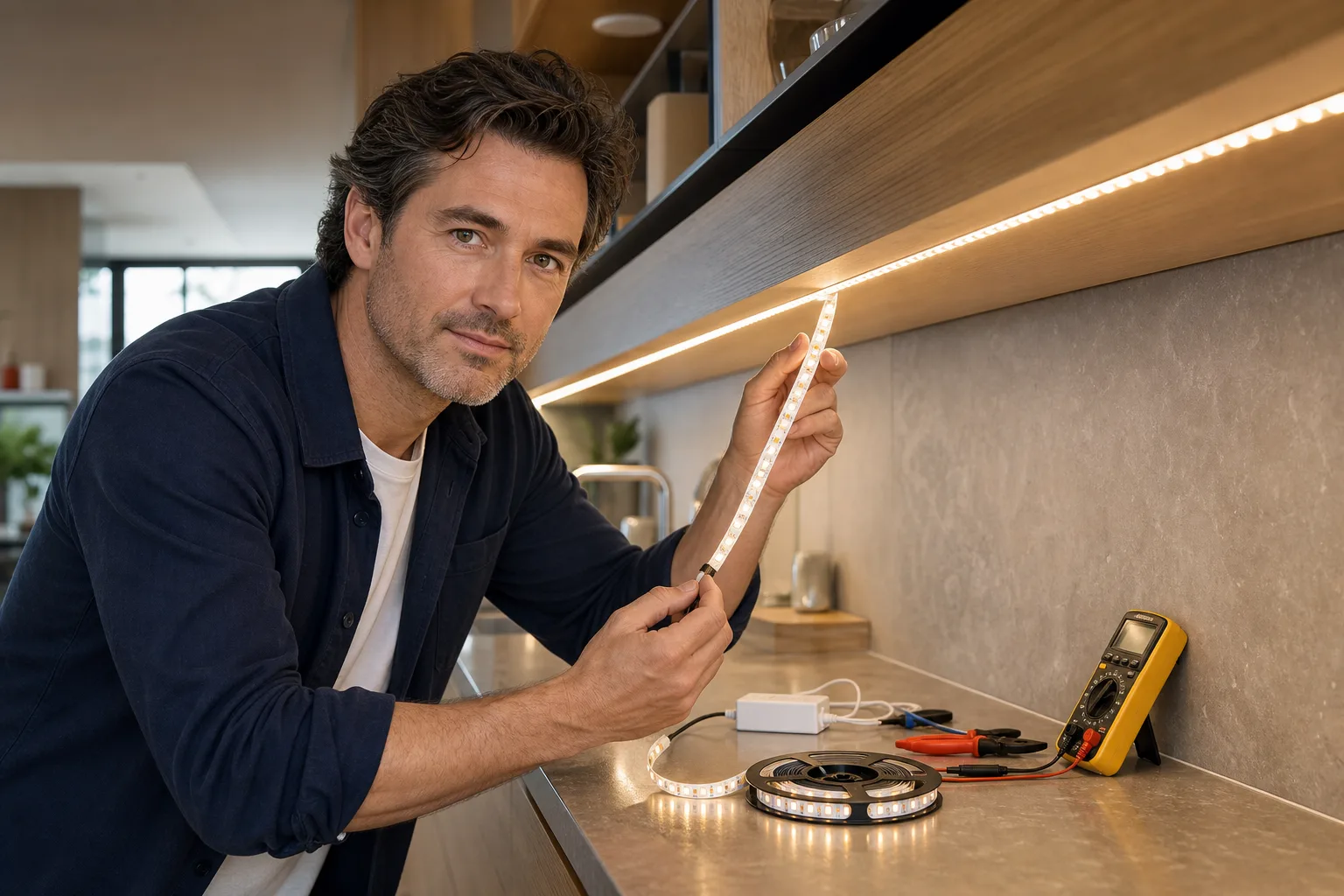
To install LED strip lights, first measure and mark the route, choose a compatible strip, power supply and controller, calculate the electrical load, and test the complete run before attaching it. Cut only at the strip’s marked cut points, keep the driver accessible, and use connectors and cables approved for the system. A plug-in, low-voltage kit can be a manageable home project; hire a licensed electrician for a hardwired driver, a new receptacle, concealed line-voltage wiring or work in a wet location.
Plan where the strip will put useful light
LED tape is a linear luminaire rather than a replacement bulb. It works best where a concealed line of light can illuminate a work surface, wash a wall, outline shelving or bounce light from a ceiling. It is less successful when exposed diodes sit directly in the normal field of view, where they can create glare and distracting points of light.
Start with the purpose of the strip. Under-cabinet lighting should reach the front half of the counter rather than brighten only the backsplash. Shelf lighting should illuminate objects without exposing the source to standing or seated viewers. Cove lighting needs enough space for the light to spread before it reaches the ceiling. The Illuminating Engineering Society advises considering off-angle views and keeping shelf-lighting sources screened; it also notes that drivers should remain accessible and ventilated. See Ross’s guides to layered lighting and planning home lighting before treating a strip as the room’s only light source.
Use the strip as the right lighting layer
- Task lighting: Place the strip close enough to a counter, desk or shelf to deliver useful light without casting shadows from a front lip.
- Accent lighting: Conceal the strip behind trim, under shelves or beside architectural details so the illuminated surface is more visible than the diodes.
- Ambient lighting: Aim the strip toward a pale wall or ceiling for reflected light. Keep an existing ceiling fixture, floor lamp or other fixture if the strip cannot provide adequate general illumination.
Make a simple route drawing that marks the power source, controller, corners, connectors and every separate strip section. Measure the actual mounting path rather than estimating from room dimensions. Add only the spare length needed to reach the next permitted cut point; LED tape cannot usually be trimmed at an arbitrary position.
Choose compatible strip, driver and controls
The components must agree on voltage, load, color type and location rating. UL Solutions identifies UL 2108 as a principal safety standard for low-voltage lighting systems and notes that complete products and individual components have different certification statuses. For a straightforward installation, use a listed kit or components that the manufacturers identify as compatible rather than assembling unrelated parts.
| Item | What to check | Why it matters |
|---|---|---|
| Strip voltage | Match 12 V, 24 V or another stated value exactly | A mismatched supply can prevent operation or damage the strip. |
| Power rating | Find watts per foot or watts per meter | This determines the required driver capacity and current. |
| Maximum run | Use the manufacturer’s limit for one continuous feed | Excessive length can cause dimming and color shift at the far end. |
| Color type | Single-color, tunable white, RGB or RGBW | The controller and number of conductors must match the strip. |
| Location rating | Dry, damp or wet location as applicable | A silicone coating alone does not establish that the complete system suits a wet location. |
| Cut spacing | Distance between printed cut marks | This controls the final installed length. |
| Control method | Compatible switch, remote, sensor, app or wall dimmer | The controller, driver and dimming method must work together. |
Select light output and color for the room
Compare lumens per foot when manufacturers publish that value; watts describe electrical demand, not brightness. Select color temperature in kelvins according to the surface and task. Warm white often suits relaxed living areas, while neutral white can make work surfaces easier to distinguish, but the appropriate choice depends on adjacent fixtures and finishes. Use the color temperature picker and Ross’s explanations of color temperature and color rendering to compare options.
For a continuous-looking line, use a channel with a diffuser and choose a strip with sufficiently close diode spacing. A channel also gives the tape mechanical support and creates a replaceable installation rather than relying entirely on adhesive. Check the channel’s internal width against the strip and connector dimensions before ordering.
Check the control path
A single-color strip may use a simple compatible low-voltage dimmer. Tunable-white and color-changing strips need controllers with the correct output channels. The U.S. Department of Energy explains that LED drivers regulate current and voltage and that driver and control compatibility is essential; dimming methods are not automatically interchangeable. Do not connect a plug-in power supply to a wall dimmer unless its instructions explicitly permit that arrangement. A hardwired dimmable driver and wall control should be selected and installed by a licensed electrician.
Calculate strip length, watts and current
Use the rating printed on the strip or its specification sheet. Do not substitute a generic watts-per-foot figure because density, color mode and product design change the load.
Total load in watts = installed length × rated watts per unit of length.
For example, a 10-foot strip rated at 4.4 watts per foot has a nominal load of:
10 ft × 4.4 W/ft = 44 W.
The power supply must meet the strip manufacturer’s required capacity. If the instructions allow a 20% planning margin, divide the load by 0.80:
44 W ÷ 0.80 = 55 W minimum supply capacity.
The 20% allowance is a design assumption, not a universal electrical-code rule. Use a larger margin if the manufacturer specifies one, and never exceed the rated load of the driver, controller, connector or cable. Ross’s LED strip power tool can perform the length-and-load calculation, but its result remains dependent on accurate product data.
Current helps with cable, connector and controller selection:
Current in amperes = watts ÷ volts.
The example’s 44-watt load draws about 1.83 A at 24 V, compared with about 3.67 A at 12 V. Lower current can make voltage drop easier to manage, but it does not override the manufacturer’s maximum run length or wiring instructions. For a long route, use approved parallel feeds, additional drivers or power injection only where the system documentation permits them.
Install and test the LED strip
1. Prepare the mounting surface
Switch off and unplug all components. The mounting surface should be smooth, stable, dry and free from dust, grease and loose paint. Use a cleaner that is safe for the finish and permitted by the tape or channel manufacturer, then allow the surface to dry. Adhesive tape is unreliable on rough masonry, dusty timber, fabric and some low-surface-energy plastics; use an approved channel or mounting clips instead.
2. Dry-fit the complete route
Hold the strip or empty channel in position without removing the adhesive liner. Confirm that doors, shelves and appliance vents will not strike it. Check viewing angles from standing and seated positions. Mark cut points, connector positions and cable exits, and make sure the power supply remains reachable for inspection or replacement.
3. Cut and connect with the power disconnected
Cut squarely through a printed cut line using clean scissors. UL Solutions notes that field-cuttable Class 2 luminaires require repeated markings so relevant information remains on sections cut from a roll. Never cut through a diode, resistor or unmarked copper trace.
Open each clip connector fully, insert the strip to the indicated depth and align its polarity or channel labels. For soldered joints, follow the strip manufacturer’s temperature, wire-size and insulation instructions. Poorly insulated or mechanically unsupported joints can short or pull away, so use purpose-made connectors if soldering is outside your skill level.
4. Bench-test before final mounting
Lay out the connected system where it cannot short against metal. Connect the strip, controller and driver in the order shown by the manufacturer, then energize it briefly. Test every color channel, dimming command and strip section. Disconnect power before correcting polarity, reseating connectors or changing the layout.
5. Mount without stretching or sharp bends
Peel back a short section of liner, align the strip and press it into place progressively. Do not pull it tight, crease it or force it around a corner tighter than its specified bend radius. Use a compatible corner connector or separate cable between cut sections when the tape cannot make the turn safely. If using a channel, secure the channel first, fit the strip, retest it and install the diffuser last.
6. Secure cables and complete the control setup
Keep low-voltage cables away from sharp edges, hinges, hot surfaces and moving drawers. Use clips that do not crush the cable. Do not bury a plug-in driver behind inaccessible construction or cover ventilation openings. Pair remotes or apps, set the preferred brightness and confirm that the system reliably restarts after power is removed.
Know when the project needs an electrician
Low-voltage output does not make the line-voltage input risk-free. Stop and use a licensed electrician if the project requires a new outlet, an altered branch circuit, a hardwired driver, line-voltage conductors inside a wall, work near damaged wiring or installation where water contact is possible. Local permits and electrical rules vary, and the authority having jurisdiction decides what is acceptable.
Use equipment marked for the actual environment. UL states that wet-location evaluation and low-voltage system certification address different hazards and ratings. An indoor strip, connector or driver should not be installed outdoors or beside a sink merely because another component appears sealed. Follow all clearances and location restrictions in the instructions and review Ross’s technical and safety guidance before concealing wiring.
- Disconnect power before cutting, connecting or repositioning the strip.
- Match the power supply’s output voltage and polarity to the strip.
- Keep the total load within every component’s rating.
- Use only marked cut points and approved connectors.
- Keep drivers accessible and provide the ventilation specified by the manufacturer.
- Do not modify plugs, defeat grounding features or use damaged cables.
- Do not assume that a component rating applies to the assembled system.
Fix common LED strip problems
| Symptom | Likely checks | Useful action |
|---|---|---|
| Nothing lights | Outlet power, switched receptacle, driver input, polarity and controller pairing | Test the outlet with a known working device, then reconnect the unpowered low-voltage side according to the diagram. |
| Only part of the strip lights | Cut-point damage, loose connector or failed section | Disconnect power, reseat the nearest joint and inspect the copper pads before replacing a section. |
| Far end is dim or a different color | Run exceeds the product limit, cable is undersized or voltage is dropping | Shorten the run or use a manufacturer-approved parallel feed or additional driver. |
| Colors are incorrect | Channel labels or connector orientation do not match | Align the strip’s positive and color-channel markings with the controller outputs. |
| Strip flickers while dimming | Incompatible driver, controller or dimming method; overloaded supply; loose joint | Check component specifications and load calculations before replacing parts. |
| Adhesive releases | Dusty, textured, damp or unsuitable surface | Remove power and remount the strip in clips or an appropriately sized channel. |
Persistent tripping, a hot or discolored connector, damaged insulation, an unusual odor or visible arcing calls for immediate disconnection and professional inspection. For non-hazardous performance issues, continue with the lighting troubleshooting guide; do not repeatedly energize a system that shows signs of electrical damage.
Frequently asked questions
Can I install LED strip lights without an electrician?
A listed plug-in, low-voltage kit can often be installed without altering household wiring if you follow its instructions. Hire a licensed electrician for a hardwired power supply, a new receptacle, concealed line-voltage wiring, damaged existing wiring or work in a wet location.
How large should an LED strip power supply be?
Multiply the installed strip length by its rated watts per foot or meter. Then apply the manufacturer’s required capacity margin. For example, a 10-foot strip rated at 4.4 watts per foot uses 44 watts; with an allowed 20% margin, the minimum calculated supply capacity is 55 watts.
Can LED strip lights be cut anywhere?
No. Cut only through the marked cut lines shown on the strip and only while power is disconnected. Cutting elsewhere can break the circuit or leave damaged conductors.
Why is one end of my LED strip dimmer?
The usual cause is voltage drop along a run that is too long or carries too much current for its conductors and connections. Follow the manufacturer’s maximum run length, or use an approved parallel feed, additional driver or shorter section.
Will any dimmer work with LED strip lights?
No. The strip, driver and controller must support the same dimming arrangement. Do not place a plug-in power supply on a wall dimmer unless the product instructions specifically allow it.
Questions & discussion
Share a question or a useful experience about this guide. Comments appear immediately. Your name and comment are public. Email is optional and stays private; reply emails are not enabled yet. Comment privacy.